FRP Grating Connections

A question that we bring up frequently in regard to FRP grating connections is whether to connect adjacent grating panels together?  FRP grating is becoming more and more popular around construction projects as an alternative to metal grating.  There are two types of FRP grating available, pultruded and molded.  Most pultruded grating is directional, meaning the loading bars need to span a specific direction while most molded grating (as a mesh) can be placed in either direction.

But a question is asked, do we connect the panels together if the panel edges do not land on a supporting beam?  This assuming the panel meets the deflection spec for a given project such as 1/4″ on a 48″ span.  We tend to think the answer should be yes.  But not everyone agrees.  See image below.  We added connecting plates to reduce the possibility of a trip hazard between FRP grating panels.  Even with a very low deflection (under 1/8″), there still is a possibility that a worker could catch a shoe if her weight caused one panel to deflect and not the other.  The image shows a plan view of grating panels (G11, G12) that have no supporting frame under the panel edges.  This is okay as the panels do meet the spec in terms of allowable deflection.  But we still felt that connecting plates would be the best approach.

So when you run into a project as described above, keep this in mind.  There is no rule the panels should be connected, but it can help to mitigate a possible tripping hazard.

FD

Grating Connection

New Telecom Spectrum and Concealment Panel Compatibility

The FCC is doing their thing and adding more spectrum for the cell phone carriers. Recent auctions have loosened up spectrum in the 700 MHz region as well as the TV repack at 600 MHz.  There is more coming and that will be above the current cellular bands such as near the microwave C band and possibly others frequencies.   So this begs the question, will RF concealment panels work in these expanded bands?  The answer depends on the frequencies (wavelengths), materials used and the type of panels.  We’ll look at these areas and try not to get too technical (and put you to sleep!).

The lower frequencies, below 2 GHz, are not especially sensitive to material types whether made of fiberglass (resin based composites) or plastics.  Both work quite well.  In fact these materials work satisfactory in all the current wireless bands.  The panel designs, whether monolithic solid panels or sandwich types, work well in the new 600/700 MHz bands as well as the current bands in use up to and including the 2.4 GHz band.

As we move above the current bands such as (the proposed) 3.5 GHz and microwave frequencies in general, materials and panel types become more of a concern.   Here is why.  First lets look at the panel design styles.

As a rule there are two types of panel designs available from different manufacturers. Both the sandwich and monolithic panel types have been around for more than 50 years. The early work was done in the radar radome field.  They discovered some curious details over the years when driving microwave through the panels.  In regard to sandwich panels, the panels were discovered to be frequency dependent.  The actual wavelength between the outer skins (measure in centimeters typically), made the sandwich panel an excellent panel if the panel was designed specifically for the frequency of interest.  The panel was therefore not useful as a broadband panel through all the microwave bands and frequencies.  Today with microwave frequencies now going up to and beyond 90 GHz, this can be an issue.  See image below.

A Sandwich

The image above is from an old article in Microwave Products Digest.  I always liked this drawing as it shows what happens with sandwich panels in general.  The skins reflect the RF signals back to the source but can have very low loss at specific frequencies or if the overall panel thickness is below 10% of the wavelength used.  Without getting into weeds of math involved, the VSWR (or reflected RF signals) can be very good (under 1 dB loss – very low indeed) for a specific frequency and very poor (10dB or worse) for frequencies outside the design wavelength.    To some degree even monolithic panels can suffer some reflections within the material.  But the phenomenon is much less pronounced and is less of a concern.

Materials also become more critical as we start to use the higher microwave bands.  The traditional FRP panel now becomes quite lossy due to its fibers and manufacturing process.  We therefore like to go to monolithic plastic panels that have good dielectric constant figures such as PTFE.  But there is no free lunch as the saying goes.  Plastic is very weak mechanically so the best solution is a hybrid FRP/plastic panel that allows microwave “windows” for the microwave paths.

Another area of concern is moisture build-up on the panel.  As we go higher into the microwave bands, the little droplets of water can greatly affect the RF path.  For a very smooth panel, this is less of a concern.  But what about if we want to put a texture on the panel (like faux brick)?  The RF antenna system designer should be prepared for losses in this case.  How much?  Difficult to say as it depends on the frequencies and panel texture.  But we have seen losses north of 10dB, which is a lot.

So as we venture into the microwave bands, we will need to be aware of what lies ahead for challenges for the RF concealment world.  As we get concealment design projects in these microwave bands we will want to pay attention to some of the details laid out here.

FD


PROPOSAL – ANTENNA CONCEALMENT DESIGN SPECIFICATIONS FOR TELECOM

Most building trades outside of telecommunications use CSI or Construction Specifications Institute format for construction specifications.  Most engineering firms are familiar with the CSI specs as it is a common practice to use these specs.  Why doesn’t the telecom industry also use the CSI specs?  It’s a mystery.  The only possible explanation that this author has is due to budget restraints.  But even that doesn’t make sense.  In this paper we will examine why it is a good idea to develop a set of standards for the concealment industry.

In the non-telecom world the correct specification falls in Division 06.  Within this specification is all the needed data for a manufacturer and contractor to follow.  But first let’s examine WHY it is important to develop concealment specifications.  See image below of an old concealment site that illustrates some of the salient issues we run into.

Old site

There are five (5) problems with this site that are obvious:

  1. The inside of the plastic sandwich panels has no protections from UV and the panels began to fail.
  2. The span between the beams (girts) is too great causing too much panel deflection.
  3. The panel vertical edges are not sealed from weather.
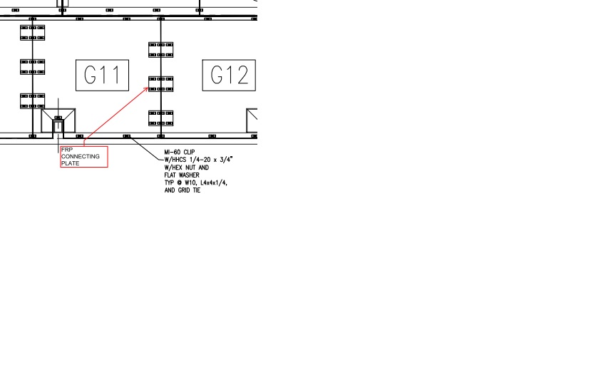
  4. The designer used FRP angles as beams
  5. The structural FRP also does not have UV protection

Item 1 – This is a common problem we see on concealment sites.  This applies to any material including FRP and especially RF screen walls.  But it applies to a lot of sites including cylinder projects.  All panels should have a UV coating applied on all exposed surfaces.  For some unknown reason we frequently see the back side of panels not coated.

Item 2 – This also is a ubiquitous problem.  The height of these panels is 8 ft and based on our knowledge of this type of panel, a 2” thick plastic sandwich panel with a foam core, the deflection in this case is excessive at design wind which in this case contributed to panel failure (not shown in this image).  We recommend a minimum design deflection of L/100 with L/180 a better target.  For example a L/180 deflection using 4ft panel supports would result in approximately a ¼” deflection at design wind.  On the panels in the above image we estimated the deflection to be approximately L/25 which is excessive and puts extreme pressure on the panel fasteners, ultimately causing pull-through and panel failure. A mid panel beam should have been employed.  Implementing a deflection standard is a good approach and can save a carrier possible law suits from flying panels.Item 1 – This is a common problem we see on concealment sites.  This applies to any material including FRP and especially RF screen walls.  But it applies to a lot of sites including cylinder projects.  All panels should have a UV coating applied on all exposed surfaces.  For some unknown reason we frequently see the back side of panels not coated.

Item 3 – This is not so obvious in the above image, however we discovered it in the inspection.  This is a problem with sandwich panels (versus single substrates).  The panels in this case were not sealed from weather at the vertical seams where they connected together.  Water ultimately worked its way into the panels with a result of de-lamination.  A similar issue is with single substrate panels (such as solid FRP panels) where the panel edges are not sealed after having been cut.  We recommend all panel edges be sealed from weather.

Item 4 – This is a common problem and designers continue to use angles as beams in flexural loading.  The pultrusion manufacturers these days try to discourage the use of angles in such an application.  The designs and some concealment manufacturers continue to design using angles.  We recommend using actual beams for flexural loads and based on load tables provided by the pultrusion makers.

Item 5 – Another ubiquitous problem that has not been addressed by telecom and has been by most of the other industries.  Although it is true that the FRP structural products have UV inhibitors in their resins, it is not enough.  The pultrusion makers recommend that their products have an additional UV coating applied when exposed directly to UV.  We recommend an industrial clear coat to be applied to all structural FRP in direct exposure to UV.  Without a UV coating the lifespan of the FRP products will be greatly reduced.

There are other areas to consider too such as fasteners, paints (and gel coats), fire ratings, design loads and connections.  So we therefore recommend the following specifications as a start for the telecom world of RF concealment.  We have left out RF specifications.

  1. UV protection on all surfaces of concealment panels
  2. Minimum panel deflection standard such as L/180
  3. Weather protection on panel edges
  4. Use FRP structural beams and not FRP angles for flexural loads
  5. UV protection for structural FRP.
  6. Fastener standards for panels and FRP connections
  7. Coatings standards such as for paints, primers and gel coats
  8. Fire rating standards – this is an area that could see some considerable changes as the new (IBC) building codes become law.  See our post about this at www.fibrdesign.com/blog for more information.
  9. Design loads should be published by the site engineer and be part of the specifications.  Otherwise the loads could be interpreted differently by the manufacturers.
  10. FRP connections is another area that should be addressed.  We see a very wide variety of FRP connections and in many cases the connections shown on the contract/construction drawings do not work.  Edge distance rules (very different for FRP than steel) as well as both number and size of fasteners (and holes) should be laid out.
  11. Zoning special requirements should be listed in the document.  Many authorities want specific measures applied and this should be spelled out.
  12. Panels to match existing – is a common note on a CD set.  It is nebulous at best and should be spelled out.  Match what?  These details should be spelled out in our specifications document.

This is a start.  The telecom industry needs to move on implementing industry standards concerning antenna concealment and related.  We would like to see a full CSI specification package for a telecom site that addresses a site from A to Z.   As noted above the FRP specs should fall into DIV 06.  But at the least a set of concealment (composite) standards should be adopted by all carriers.  The current situation is a mess and tends to get worse when an AE passes the buck with “Design By Others” for composite projects.  We know the carriers can dictate this sort of thing.  Implementing concealment specs will result in a better lifespan for a given site and allows all concealment vendors to work from the same data.  Another solution is to allow FiberDesign to design a project/site, which would include a specification document.   The time to deal with this is now.  We can help.

Peter Sturdivant

Working with Composites Fire Ratings

I am not an expert on the subject of fire ratings, but I have been exposed to it over the years and sooner or later some of it sinks in.  There are several agencies that oversee this area including and not limited to the International Building Code (IBC), marine agencies such as the US Coast Guard (USCG), NFPA, ASTM and UL.  The IBC, NFPA and UL tend to have an international presence with many countries that subscribe to their codes.  ASTM tends to address actual testing methods like they do for engineering codes.

Almost all markets have some needs for fire rated (FR) composites.  I will address the industrial and architectural markets here, although the other markets have similar needs from marine to transportation to consumer products.

A common test that is referenced in project specifications is ASTM E84. There are a couple different classes such as Class 1 and Class 2 (sometimes referred to as Class A, B or C).   When a FR code is specified, it typically is Class 1.  The important criteria here is the Flame Spread and the Smoke Index.  To meet Class 1 flame spread the material must meet the 25 index and for smoke, the 450 index.

Here is where it gets interesting.  Many FR FRP materials meet the flame spread figure, but not the smoke index.  This is especially true for isophthalic resins (ISOFR) which are common with the FRP pultrusion makers.  Not that they do not have a solution for a low smoke product….some of them do have a product.  I don’t know for sure why it is uncommon to find low smoke resins, but it is tough to pass the test.  The testing can also be expensive.  ASTM testing tends to be fairly reasonable with some exceptions while the NFPA has very tough guidelines and tend to have very expensive tests costing $20K or more.  Its also possible that for most pultruded applications, the product is outside such as on buildings or at industrial sites like water plants.

The resin manufacturers tend to offer testing on their own resins.  This is very helpful to a laminate manufacturer.  It should be noted that resin makers like Polynt offer both gel coat and standard resins with tested FR ratings.  And finally, FR is available in most of the common resin types like polyester, epoxy and vinyl ester.

So next time you see a product that lists a feature as Class 1, don’t assume it meets both index and smoke.  You can count on it meeting the Flame Spread, but not necessarily the Smoke Index.  In the future we will address the NFPA and their standards.

Peter Sturdivant